Packet Tracer Guide
Cisco Packet Tracer is a network simulator, and the CCNA labs on this site run in it. This guide builds one network from start to finish:
- One 2911 router.
- One 2960 switch.
- Two PCs.
Install Packet Tracer
Create a free account at Cisco Networking Academy.
Sign in, open the Resource Hub and download Packet Tracer for your operating system.
On Ubuntu, install the package you downloaded:
1$ sudo apt-get install ./CiscoPacketTracer_901_Ubuntu_64bit.debStart it with
packettracer, or from your applications menu.Answer No to the question about running multi-user.
Click LOGIN.
- Your browser opens the Networking Academy sign-in.
- When it says you have logged in, close the tab and go back to Packet Tracer.
Read the Packet Tracer window
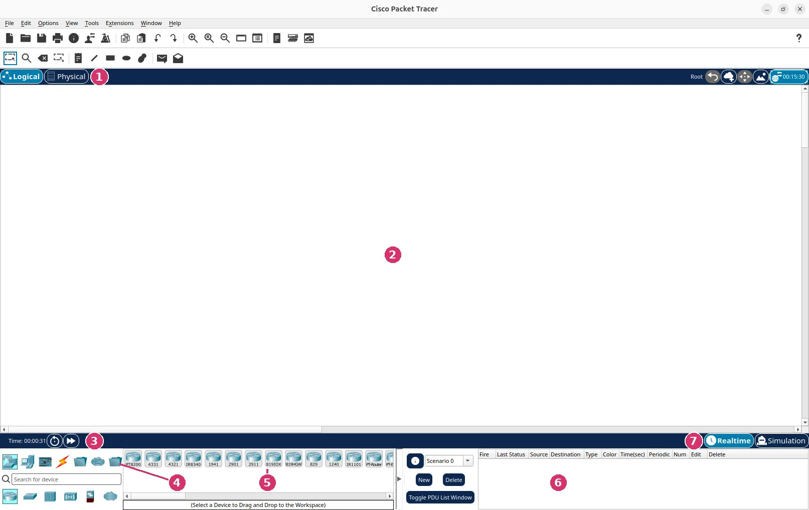
- Logical and Physical tabs: the network as a diagram, or as devices in rooms and racks. These labs use Logical.
- The workspace: where the devices and cables go.
- The clock: the simulated time, which the two buttons reset and speed up.
- Device categories: routers, switches, cables and the rest.
- Device models: the models in the chosen category.
- The packet list: the test packets you create.
- Realtime and Simulation: the network running normally, or one packet at a time.
Place the devices
Choose a category, then drag a model from the list onto the workspace.
Packet Tracer lists many models, and these four cover the CCNA labs:
- 2911:
A router with three built-in Gigabit Ethernet ports and four slots for WAN cards.- Use it for every router in a lab.
- The built-in ports are enough, so it needs no cards.
- A routing lab places two or three of them.
- 2960-24TT:
A Layer 2 switch with 24 Fast Ethernet and two Gigabit Ethernet ports.- Use it for VLANs, trunks and Spanning Tree.
- It takes no cards.
- 3560-24PS:
A Layer 3 switch, which can also route between VLANs.- Use it only where a switch must route, such as Layer 3 EtherChannel.
- It takes no cards.
- PC-PT:
A simulated desktop computer.- Use it for every end device.
Place one 2911, one 2960-24TT and two PC-PT.
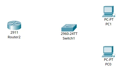
Open a device
Click a device to open its window. It has these tabs:
- Physical:
The device's front and back panels, and the cards that fit it. - Config:
Forms for common settings.- Each form shows the IOS commands it is equivalent to.
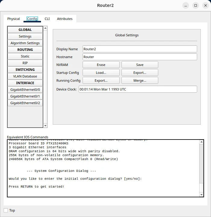
- CLI:
The device's command line.
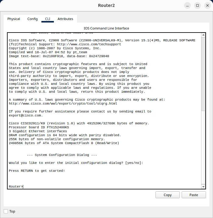
A router boots when you place it, and the CLI tab shows the boot. The Config tab and the command line stay closed until it finishes.
Add a card to the router
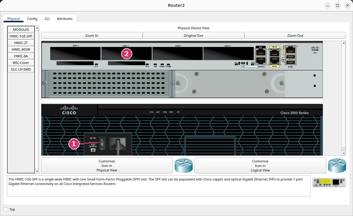
A card is installed with the device's power off, in the Physical tab:
- Click the 2911 and open Physical.
- Click the power switch on the picture of the router, marked 1 in the picture.
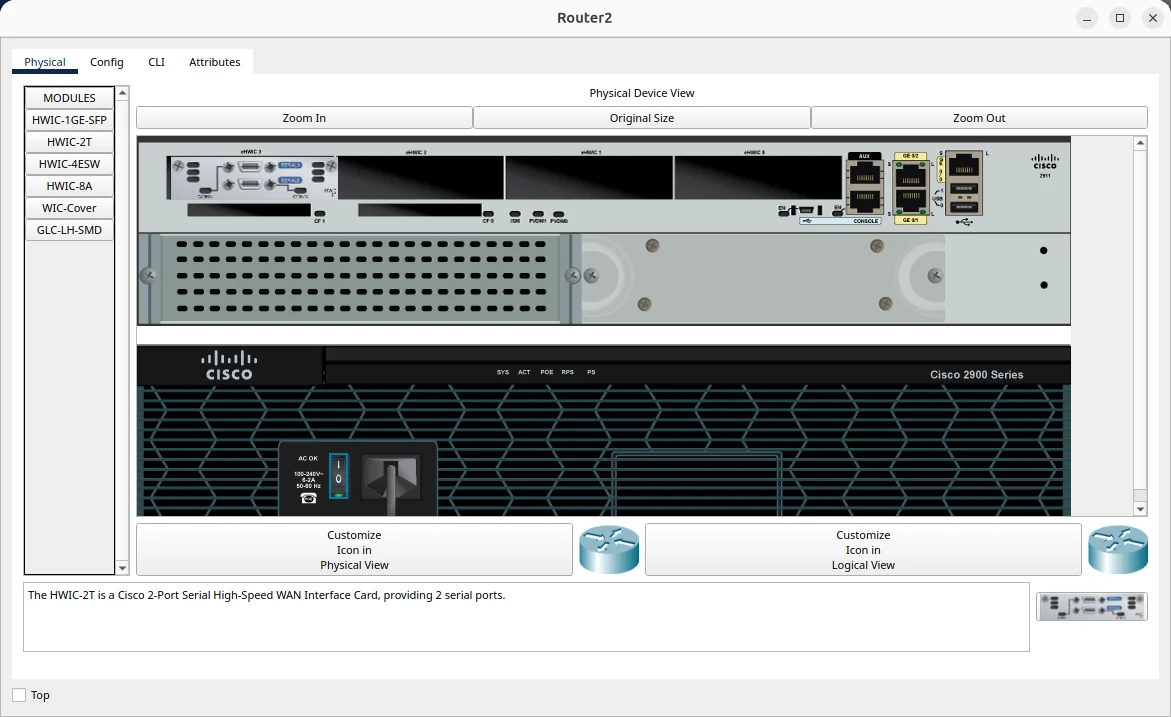
- Click HWIC-2T in the list. It is a card with two serial ports.
- Drag the card from the picture at the bottom right into an empty slot, marked 2 in the picture.
- Click the power switch again.
Recognise the cable icons
The cable list has thirteen icons, in this order from left to right:
| Icon | Colour and shape | Cable | Used for |
|---|---|---|---|
 | Orange lightning bolt | Automatic | Packet Tracer picks the cable. The labs leave it alone, since picking is the skill being practised |
 | Light-blue curve | Console | A PC's RS-232 port to the Console port of a router or switch |
 | Solid black line | Copper Straight-through | Ethernet between two different kinds of device |
 | Dashed black line | Copper Cross-over | Ethernet between two similar devices |
 | Orange line marked S | Fiber, single-mode | Fiber ports whose module is single-mode |
 | Orange line marked M | Fiber, multimode | Fiber ports whose module is multimode |
 | Dashed black zigzag | Phone | Modem ports. Not used in the labs |
 | Blue zigzag | Coaxial | Coaxial ports. Not used in the labs |
 | Red zigzag with a clock | Serial DCE | A WAN link between serial ports. This end must set the clock rate |
 | Red zigzag | Serial DTE | The other end of a serial link |
 | Light-green line | Octal | Eight console lines from one port. Not used in the labs |
 | Olive line | IoE Custom | Things and microcontrollers. Not used in the labs |
 | Purple line | USB | Things and microcontrollers. Not used in the labs |
Pick the cable for a link
Two questions pick the cable:
- What is the port called? FastEthernet and GigabitEthernet take copper, Serial takes the red cable, and Console takes the light-blue one.
- For copper, what is at each end? PCs and routers send on one pair of wires, and switches and hubs send on the other.
- One end from each group takes straight-through.
- Two ends from the same group take cross-over, which crosses the pairs.
| Link | Cable |
|---|---|
| PC to switch | Straight-through |
| Router to switch | Straight-through |
| Switch to switch | Cross-over |
| Router to router, on Ethernet ports | Cross-over |
| PC to router | Cross-over |
| PC to PC | Cross-over |
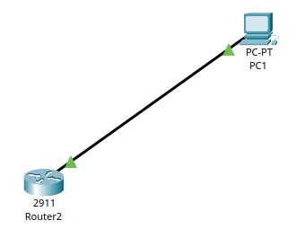
A copper cable of the wrong type can still come up. This PC and the router's port are joined by straight-through, where the table gives cross-over, and both ends are green, because these ports swap the wire pairs themselves (Auto-MDIX). The labs still use the cable the table gives.
Connect the cables
To connect two devices, choose the cables category, click a cable, click the first device and pick a port, then click the second device and pick a port.
Connect this network with Copper Straight-through:
| From | To |
|---|---|
| PC0 FastEthernet0 | The switch's FastEthernet0/1 |
| PC1 FastEthernet0 | The switch's FastEthernet0/2 |
| The switch's GigabitEthernet0/1 | The router's GigabitEthernet0/0 |
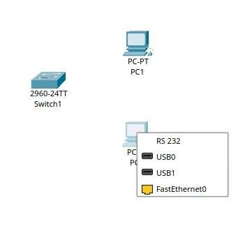
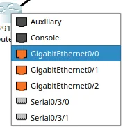
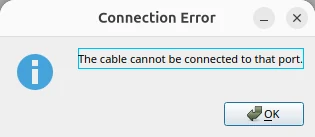
Packet Tracer refuses a cable that a port cannot take:
Read the link marks
A mark on each end of a cable shows the state of that link:
- Green triangle: the physical link is up. It says nothing about the line protocol.
- Blinking green triangle: the link is carrying traffic.
- Red triangle: the link is down, with no signal detected.
- Amber circle: the switch port is blocking, because of Spanning Tree.
- Black circle: a console cable is on the correct port.
This is the network just after connecting it:
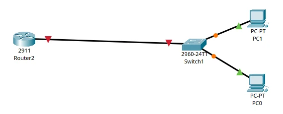
- The PC links are amber at the switch, because Spanning Tree takes over 30 seconds to start forwarding on a port.
- The router link is red at both ends, because a router's ports start shut down until each one gets
no shutdown.
Configure the router
Configure the router on its CLI tab. Press Enter to reach the prompt, then:
 1Router>enable
 2Router#configure terminal
 3Enter configuration commands, one per line.  End with CNTL/Z.
 4Router(config)#interface GigabitEthernet0/0
 5Router(config-if)#ip address 192.168.1.1 255.255.255.0
 6Router(config-if)#no shutdown
 7
 8%LINK-5-CHANGED: Interface GigabitEthernet0/0, changed state to up
 9
10%LINEPROTO-5-UPDOWN: Line protocol on Interface GigabitEthernet0/0, changed state to up
11
12Router(config-if)#end
13Router#copy running-config startup-config
14Destination filename [startup-config]?
15Building configuration...
16[OK]
17Router#show ip interface brief
18Interface              IP-Address      OK? Method Status                Protocol
19GigabitEthernet0/0     192.168.1.1     YES manual up                    up
20GigabitEthernet0/1     unassigned      YES unset  administratively down down
21GigabitEthernet0/2     unassigned      YES unset  administratively down down
22Serial0/3/0            unassigned      YES unset  administratively down down
23Serial0/3/1            unassigned      YES unset  administratively down down
24Vlan1                  unassigned      YES unset  administratively down down
At Destination filename [startup-config]?, press Enter to accept the name in brackets. IOS reads anything you type there as a file name, so answering y fails with %Error copying nvram:y (Invalid argument).
The last command lists every interface:
GigabitEthernet0/0isupandup: the physical link and the line protocol are both working.administratively downmarks a port that has not receivedno shutdown.Serial0/3/0andSerial0/3/1are the two ports of the HWIC-2T card.
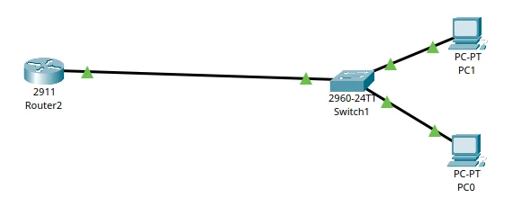
Once the router's port is up and Spanning Tree has finished, every mark on the network is green:
Configure the PCs
Configure each PC on its Config tab, in two places:
- FastEthernet0, under INTERFACE, holds the address and the mask.
- Settings, under GLOBAL, holds the default gateway. A PC without one shows
0.0.0.0inipconfig.
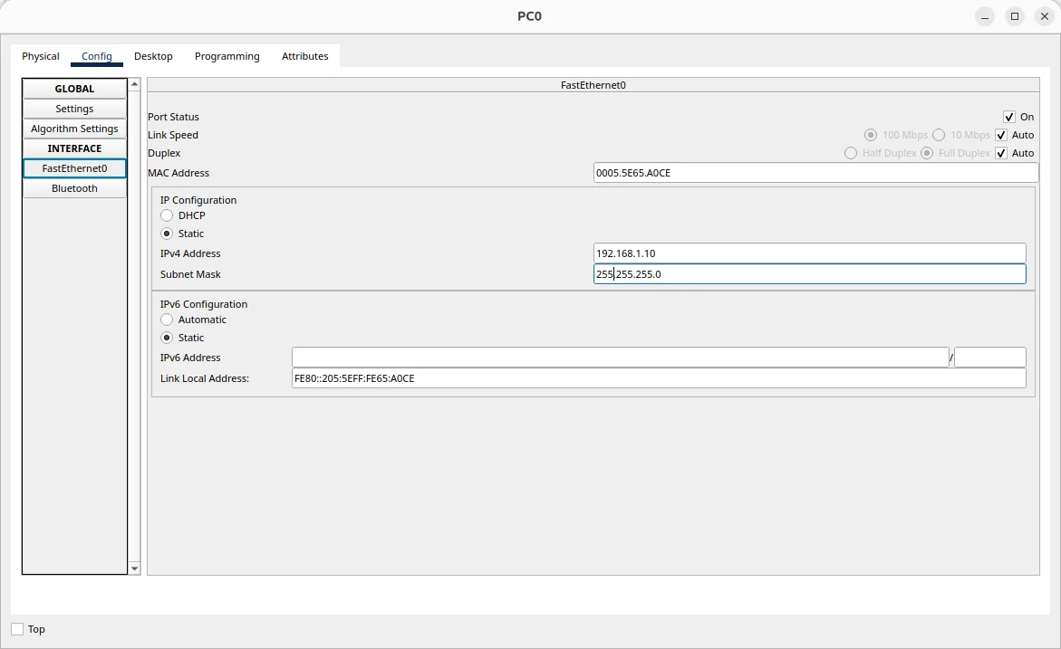
| PC | IPv4 address | Subnet mask | Default gateway |
|---|---|---|---|
| PC0 | 192.168.1.10 | 255.255.255.0 | 192.168.1.1 |
| PC1 | 192.168.1.11 | 255.255.255.0 | 192.168.1.1 |
Then open Command Prompt on PC0's Desktop tab and ping the router and the other PC:
1C:\> ping 192.168.1.1
2C:\> ping 192.168.1.11


Save the network to a file
Packet Tracer keeps a network in one file, which only Packet Tracer can read:
.pkt:
A saved network: its devices, cables and configuration.- It is a binary file, so
git diffshows nothing useful about it.
- It is a binary file, so
.pka:
An activity: a network with instructions and scoring.
On Linux, Packet Tracer keeps its own settings, logs and saved files in ~/pt.
Save a network with File → Save As:
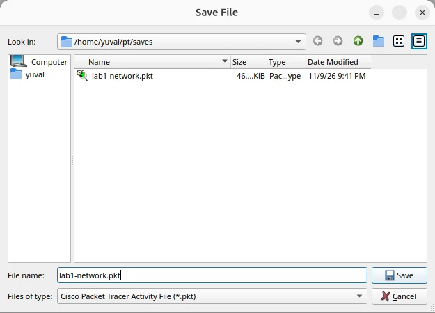
A .pkt keeps the running configuration, including changes never copied to the startup configuration. This router was renamed LAB1 without copy running-config startup-config, then the file was saved and reopened, and the prompt still says LAB1:

The startup configuration still matters, because a device that is turned off and on reads its configuration from there. Anything not copied to it is lost at that point.
Take a configuration out as text
A device's configuration can leave Packet Tracer as plain text. On its Config tab, under Settings:
- Startup Config has Load and Export.
- Running Config has Export and Merge.
The show running-config command prints the same kind of text in the CLI tab, and the tab's Copy button takes it out. This is the part of it that holds two of the router's ports:
 1interface GigabitEthernet0/0
 2 ip address 192.168.1.1 255.255.255.0
 3 duplex auto
 4 speed auto
 5!
 6interface GigabitEthernet0/1
 7 no ip address
 8 duplex auto
 9 speed auto
10 shutdown
11!
A working port has no no shutdown line, because IOS writes only shutdown, on the ports that are shut down.